Sezione disponibile solo in inglese
Self-driving car
The intent of this project is to build a self-driving car
The Covid-19 pandemic has changed a lot our habits. This situation has forced us to stay more time at home. I'm not used to spend time watching TV or worse doing nothing at all, thus I've thought to start a new project.
When I decided to build a self-driving car I didn't even know where to start, I didn't know how exactly it had to be built or how it could drive by itself.
The first thing I did was to look for other projects to take some inspiration from them to decide whether it was something within my reach or not.
Once decided that I could realize this project, I started to make some simulations at the PC related to computer vision to test how the car could recognize the lane.
Because I'm sure that this project will take quite a while to be accomplished, I've decided to track it as a blog topic, writing something new anytime I will do a significant step further or I will have something that could be of interest to say.
19 May 2021
Having four motors and no steering wheels, to make the car turn it is necessary to have a different speed between the left and right motors. I've written the code to turn left and right, but testing the functionality I've faced a problem: the right motors were running while the left ones were not.
My first thought was about some disconnected wires, but all of them were connected. I reverted the code to have the car moving straight and it did work. Trying again the code to turn, three motors were running and one was not. This new behavior led me to the correct guess, I was setting the gap between the duty cycle for the left and the right motors too high.
Some of my tries:
- Duty cycle for right and left motors 110, all run
- Right 130 and left 110, the motors run at a different speed
- Right 160 and left 110, right motors run, left motors don't
- Right 200 and left 150, the motors run at a different speed
- Right 200 and left 140, right motors run, left motors don't
Currently, the front motors are connected to one DRV8833, and the rear to the other. This configuration decided for space convenience must be changed, I have to connect the right motors to one DRV8833 and the left ones to the other. In this second configuration, the problem will not arise because, at any given moment, the duty cycle for both the channel of each driver will be the same and I will be able to use any speed on each side of the car.
12 May 2021
Now that each of the four motors is driven on its own by two DRV8833, the wiring is appropriate, and everything is working, it is time to start coding.
I've decided to publish the code on Github, you can find it following this link .
At the time of publishing this post, the code consists of the setup for the pins in use, those for the motors and the optocouplers, the setup for the PID control, and at last a test to move the car forward with the PID supervision to have all the wheels turning at the same RPM, but the values fluctuate too much at the moment, I will tune differently the PID's parameters after some tests.
13 Apr 2021
As I started to work on this project I planned to use one dual H-bridge driver to manage the four motors, I thought to connect in parallel the two right motors to one L298N output and the left motors to the other.
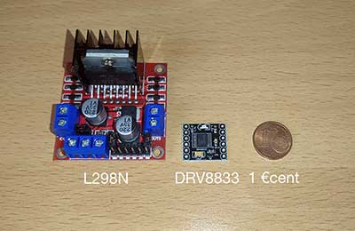
In light of the fact that I need to implement the PID control, I have to control each motor separately, thus, I need two dual H-bridge drivers, and to use two L298N is not an option, the driver is too big.
The logic replacement would be the TB6612FNG because it works as the L298N, and no change to the code would be necessary, but I will not use it.
My choice is the DRV8833 , because it occupies less pins on the microcontroller.
04 Apr 2021
Yes, unexpected to me because of my inexperience.
I've got the car moving, I've written a simple sketch which in the loop only sets the motors to run forward for two seconds, stops the motors, sets them to run backward for two seconds, stops the motors. So what could be wrong with this? Some of you might have correctly guessed: the car doesn't move in a straight line.
I was too optimistic thinking that four cheap motors could run all at the same exact speed. Anyway, reading to find a solution I've learned that you can not even rely on good quality motors.
The response to my search for a solution is that what I was doing is known as Open-loop control .
The good news is that I already have what I need to implement the closed-loop control: the optocouplers which I planned to use to control the car speed, can give the proper feedback to adjust each motor PWM frequency to have all of them moving at the same speed, or at least at a speed not too much different from each other.
Now I have to study the PID controller , and how to implement it for the ESP32.
Luckily there is a library written for Arduino which is possible to adapt with almost no effort.
22 Mar 2021
Now that I'm more confident about the possibility to succeed with this project, I've bought some parts to start building the car.
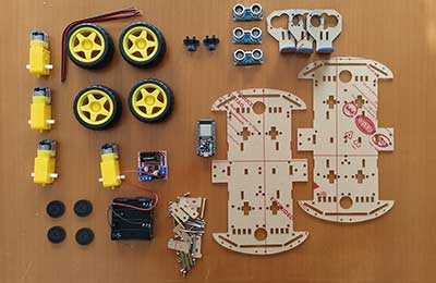
To build the car I've bought a kit consisting of the car chassis made in plexiglass, and four DC motors. In truth, my first thought was to buy a car with steering wheels, but I couldn't find an appropriate one. To drive the motors I've opted for the L298N dual H-bridge. I've also bought four optocouplers based on the LM393 dual differential comparator and a few ultrasonic ranging modules HC-SR04
Lastly, the most important component, the microcontroller.
My first choice was for the Arduino Uno , because I already had one, but planning the wiring, which sensors to use, how to control the motors, and how to communicate with the PC, I realized that it was not the microcontroller to use.
Looking for an alternative, I came across the ESP32 , which I didn't know, many pins to use, all of them with PWM capability, built-in WiFi and Bluetooth, and that became my choice.
13 Mar 2021
Before buying the required components, there is something I want to be sure to be able to accomplish, that is lane recognition.
At first I took a video while driving with my car to have something to work on, but I soon realized that it was not necessary to recognize a real road, there were too many details and it is an environment where my autonomous car will not drive.
For this reason, I've decided to draw a track using Blender and to render a video of one lap having the camera not keeping the center of the lane.
The decision to have the camera moving away from the center of the lane will help to simulate the need for the car to correct its direction because I want that the real car will try to keep the center of the lane.
Now that I have a clean video, I can try to recognize the lane and to understand the deviation from the center.
To achieve this task, I've decided to use Python and OpenCV .
After a few days reading documentations, watching other videos to obtain some useful hint and trying to write my own code, I've finally written a working script which recognizes the sidelines, understands the direction where a bend heads and the deviation from the center of the lane.
At the moment the evaluation of the deviation from the center is at a very primitive stage, it works as follow:
- With OpenCV I can recognize the lines on the frame and get their parameters.
- Lines with a positive slope are considered as placed to the left of the frame and added into an array, those with a negative slope are considered as placed to the right and added into another array. This is because of perspective.
- The script calculates the average slope both for the left and right lines providing two new lines.
- The script now calculates the X coordinate where the two lines intersect each other.
- The deviation will be the distance of the previous X coordinate from the center of the frame.
I will modify this algorithm, but for the moment I know that my car will be able to see the road, which was my concern.
Follows a video showing the simulation.


